
1. Introduction
The Advantech AOM-2721 is an Open Standard Module (OSM), specifically a Computer-on-Module that adopts the OSM 1.1 form factor. It’s designed to be a compact and
integrated computing platform, particularly suited for embedded applications
and edge AI.
2. Prerequisites
Hardware
- One AOM-2721 OSM development kit powered by the Qualcomm Dragonwing™ QCS6490
- Qualcomm 8-core Kryo CPU, up to 2.7GHz
- Hexagon™ Tensor Processor with 12 TOPS AI capability
- Adreno VPU 633, 4K30 Encode / 4K60 Decode (H.264/H.265)
- Adreno GPU 643, OpenGL ES3.2 / OpenCL 2.0
- Onboard 8GB LPDDR5 memory (8533MT/s)
- Onboard 128GB UFS + 128GB eMMC storage
- Featured I/O interfaces:
- 1× HDMI 1920×1080@60Hz
- 1× DP 1920×1080@60Hz
- 2× 4-Lane MIPI-CSI
- 1× USB 3.2 Gen1
- 2× PCIe Gen3 x1
- 1× PCIe Gen3 x2
- 2× GbE
- One x86 development machine with 16GB RAM and 350GB storage
- One Full-HD HDMI monitor and HDMI cable
- One USB mouse and keyboard set
Software:
- Installing the Yocto OS (via a Ubuntu host machine)
- Setting up AI runtime on the AOM-2721
3. How to Set up the Boot Switch
- For example, the pictures below show micro switches on the AOM-2721 Dev. Kit
which are used during the flashing process and should be common
to any AOM-2721 compatible device.
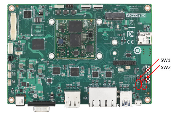
Advantech AOM-2721 Dev. Kit Switches
- In the following setup instructions, the AOM-2721 Dev. Kit is the actual
device shown in the pictures. Other devices based on the AOM-2721 OSM may look
slightly different.
3.1 (Optional) Flashing Your AOM-2721 OSM
Your actual device containing the AOM-2721 OSM may already ship with a running Yocto-based image flashed into it.
If so, you can optionally proceed to Step 3.If you need to flash your device, please follow the instructions provided in
AOM-2721 Yocto User Guide → Quick Start.Official Yocto images created by Advantech for the AOM-2721 OSM can be found here:
AIM-Linux Qualcomm Yocto OS Release Notes.Please download the image version aom2721a1_yl01301_k0606052_q6490_08g or above.
Once the flashing process is complete, proceed to Step 3 below.
3.2 (Optional) Building Your Own Yocto Image for the AOM-2721 OSM
Some users may prefer to build a custom Yocto image for their AOM-2721 OSM.
In this case, please refer to the following instructions:
Build YOCTO Image by Build Script
to set up a Yocto build host and build a compatible image for your AOM-2721.
4. Starting Up Your AOM-2721 OSM and Connecting to the Internet
4.1 Overview
This section describes how to power on your AOM-2721, establish a network connection, and install the Edge Impulse CLI.
4.2 Step-by-Step Setup
-
Install the Edge Impulse CLI on your host computer.
-
Connect the power supply to the back of the AOM-2721 OSM.
-
Connect the serial console:
- If your device is equipped with a COM1 serial port, connect it to your host PC’s USB port via a Serial-to-USB converter (a gender changer may be required).
Advantech AOM-2721 Dev. Kit — USB over Serial-to-USB
-
Open a serial connection between your host computer and the board.
You can do this directly using the Edge Impulse CLI:edge-impulse-run-impulse --raw -
Press the power button to start the boot-up process.
-
Log in after 30–60 seconds when you see the login prompt in your serial terminal:
- Username:
root - Password:
oelinux123
- Username:
-
Set up a network connection:
- Option A: Connect an Ethernet cable.
- Option B: Connect via Wi-Fi:
- For Qualcomm Linux earlier than v1.3:
Edit thewpa_supplicant.conffile. - For Qualcomm Linux v1.3 and later:
Usenmcli.
- For Qualcomm Linux earlier than v1.3:
-
(Optional) Continue setup over SSH:
-
Find your device’s IP address:
ifconfig | grep "inet addr:" | grep -v "127.0.0.1"Example output:
inet addr:192.168.1.38 Bcast:192.168.1.255 Mask:255.255.255.0 -
Log in using SSH (default password:
oelinux123):ssh [email protected]
-
5. Installing the Edge Impulse Linux CLI
-
On the AOM-2721 SOM, install the Edge Impulse CLI and required
dependencies by running the following commands:$ wget https://cdn.edgeimpulse.com/firmware/linux/setup-edge-impulse-qc-linux.sh
$ sh setup-edge-impulse-qc-linux.sh
6. Connecting to Edge Impulse
-
After installing all dependencies, run:
$ edge-impulse-linux
This will launch a wizard which asks you to log in and select an Edge
Impulse project. If you want to switch projects or use a different camera (e.g.
a USB camera), run the command with the —clean argument.$ edge-impulse-linux –clean

7. Verifying that your device is connected
-
That’s all! Your device is now connected to Edge Impulse. To verify,
go to your Edge Impulse project and click Devices. Your device should be listed here.
For example:
Go to https://advantech.edgeimpulse.com/studio/677676/acquisition/training
8. Edge Impulse Account Creation and Project Setup
- Please create your account first.
If you already have an account, please jump to 5. Data Acquisition and Upload.
Step 1:
The Advantech-branded Edge Impulse sign-up page, where users create an account by entering a username, company email, job title, and password, completing the CAPTCHA, and accepting the terms of service before clicking “Sign up.”

Step 2:
The Advantech-branded Edge Impulse log-in page,where users enter their username or company email address and click “Next” to proceed with authentication.
Additional options include resetting the password or creating a new account.

Step 3: Creating a new project in the Edge Impulse platform by entering the project name “Automated Optical Inspection,” selecting the Enterprise type, and choosing Public or Private settings before clicking “Create new project".

Step 4: The project homepage of “Automated Optical
Inspection” in the Edge Impulse platform, where users can add existing data,
collect new data, or upload a model, as well as follow tutorials to quickly
build a model.

9.Data Acquisition and Upload
Step 5: In the Edge Impulse project, under the “Data
acquisition” page, users can click “Add data” to start building the dataset or
connect a device to collect new image data.

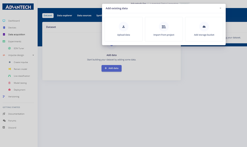
Step 6: In the “Add existing data” menu, users can
choose from three options to add data to the project: uploading data, importing
from another project, or using a storage bucket.
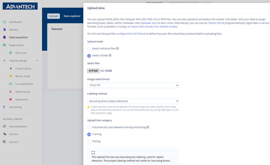
Step 7: On the “Upload data” page, users can choose to
upload individual files or a folder, specify whether the data belongs to the
training or testing set, and define labels by inferring from filenames, leaving
them unlabeled, or entering them manually. After configuration, click “Upload
data” to begin the upload.

Step 8: Selecting the local training folder (train) to
upload to the Edge Impulse platform for building the training dataset.

Step 9: On the “Upload data” page, setting the labeling
format to YOLO TXT and choosing the labeling method as bounding boxes for
object detection tasks.
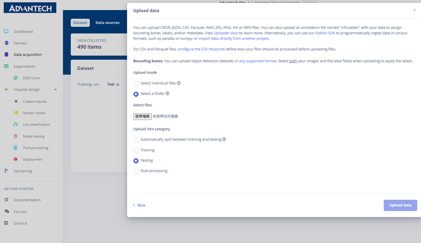
Step 10: Uploading the testing dataset to the Edge
Impulse platform and assigning the data category as “Testing.”
Step 11: Completing the upload of the testing dataset,
setting the format to YOLO TXT and using bounding box labeling to prepare a
complete testing set.

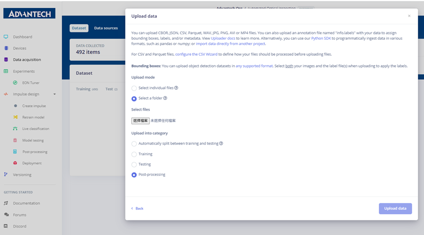
Step 12: Uploading post-processing data to the Edge
Impulse platform and categorizing it under Post-processing.
Step 13: Completing the upload of post-processing data
with YOLO TXT format and bounding box labeling method.

Step 14: The “Data acquisition” page showing 500
collected data items, categorized into Training, Testing, and Post-processing
sets, with options for editing labels, moving items, and enabling or disabling
data.

10.Data Labeling and Preparation
Step 15: The batch edit labels (Edit labels) function,
setting 490 samples to the “crooked” label, with other defect categories such
as over soldering and tombstone available from the dropdown menu.

Step 16: Viewing uploaded images in the dataset, with the
sample image and bounding box annotations shown on the right, such as labeling
the defect as crooked.

Step 17: Using the “Edit labels” function to assign the
selected image as over soldering, with the updated label displayed on the
right.

Step 18: Batch labeling images with the tombstone defect,
with the updated annotations displayed on the right.
